PROTOTYPEThe "Rotunda", turntable, or as many railway workers called it "route" was a pit with a rotating bridge whose original function was to turn around the old steam locomotives. At the same time, it was used to place maintenance and repair workshops around it, acting then as a distributor from the track or access tracks to any of the workshops, warehouses, or sidings. Later on, although it was no longer necessary to reverse the direction of diesel or electric locomotives with two ends, it continued to be used to take advantage of the already installed workshops around it (in some cases, even a catenary was installed). The roundabouts could be operated manually but were usually motorized.
MODEL
The roundabout is one of the most attractive railway facilities from an aesthetic point of view for modelers and railway enthusiasts, but also because it is an ideal area for maneuvering with locomotives.
 Placa giratoria Märklin 7286
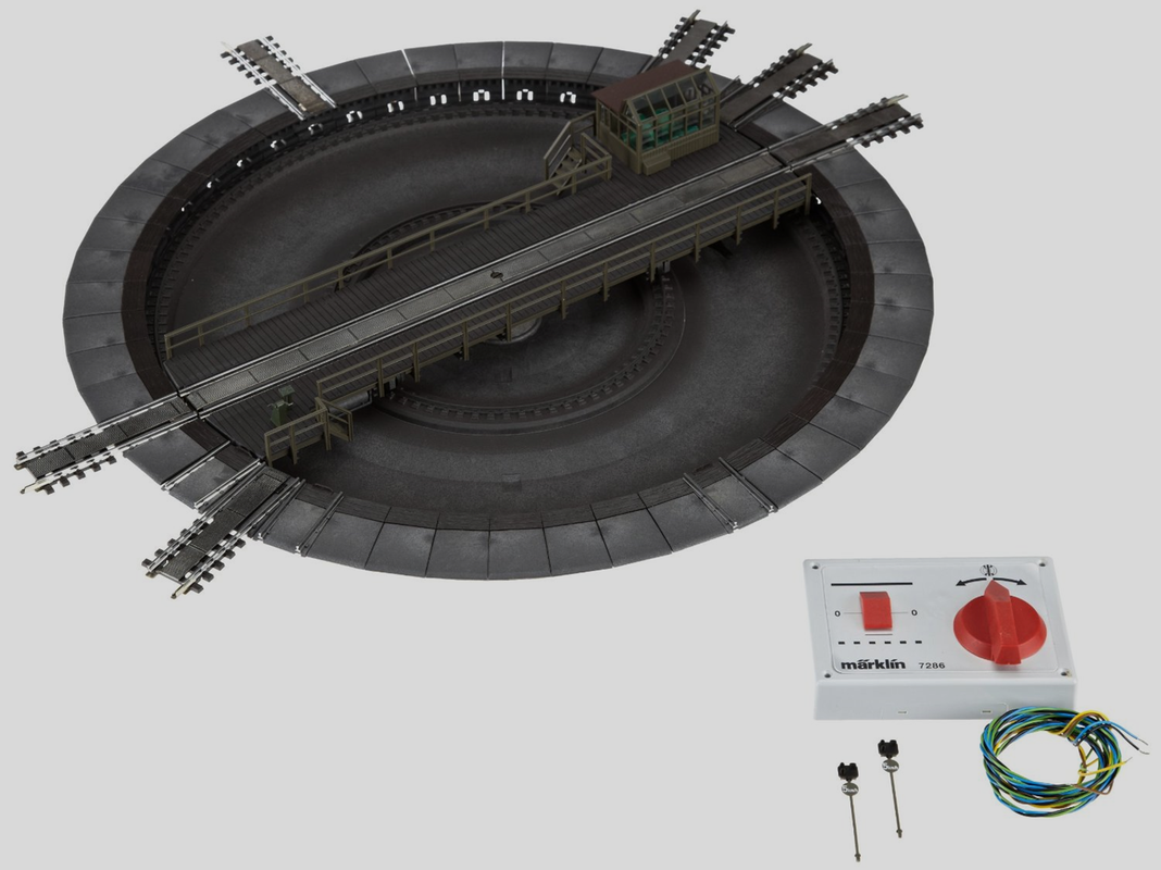
The Märklin 7286 model was made in cooperation with the Fleishmann company. It has been present in all Märklin catalogs from the year 2000 to today, although since 2002 it has been delivered with a technically modified version. It is a motorized and analog model that can later be digitized if desired. In addition to being able to operate manually if necessary, in analog it has a remote control box [for use at 16v] that allows for automatic step-by-step turning or continuous turning, to the left or right. The pit has an aged gray tone around which the moving parts for each of the 48 locking segments are located, some of which will have tracks and others will not, depending on how we configure them. On the bridge, there is a manual control post next to an electric control stand and on the opposite side, a control hut that houses the simulated machinery while the real electric motor is located out of sight, under the bridge. It also has 2 simulated and non-operational signals, one on each side of the bridge.
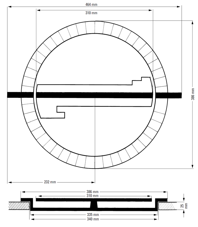
It has 48 possible locking positions arranged at 7.5º each. It has an outer diameter of 386 mm, a diameter for embedding in the panel of 340 mm, and a rotating bridge of 310 mm in length.
Märklin also offers an expansion set of segments with tracks with the code 7287 as well as a digital control decoder 7687. (there are also other decoders from other manufacturers that are compatible and sometimes with expanded functions. See later.)
The track segments are type K which does not pose any problem for installations of track type C or M since the independent siding tracks can be type K ref. 2206 and for the tracks that have communication with the installation in track C the K-C adapter track ref. 24922 is used and for track M the K-M adapter track ref. 2291.
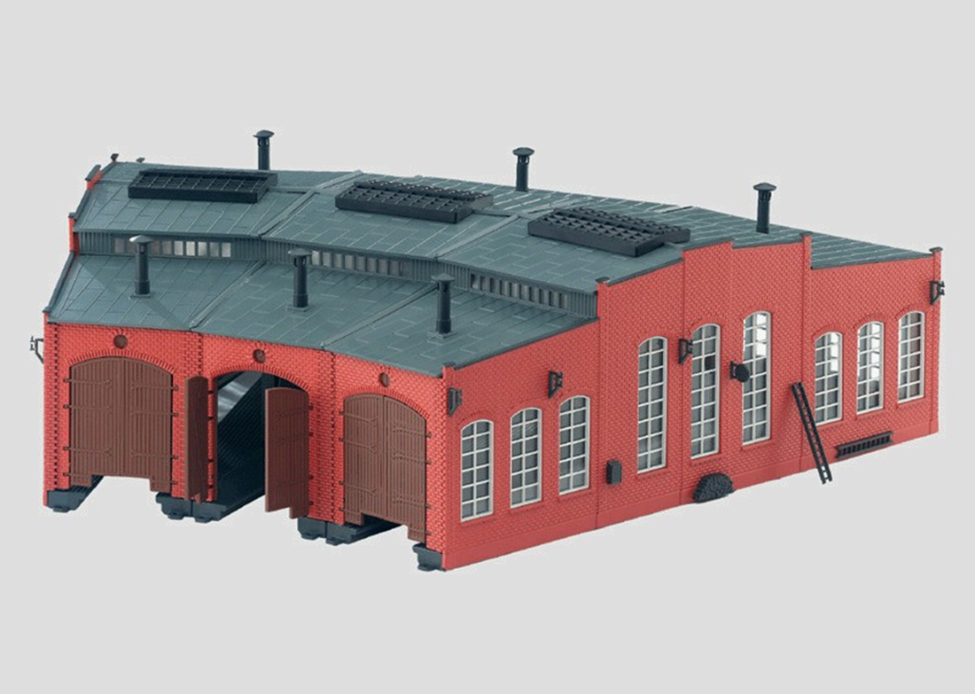
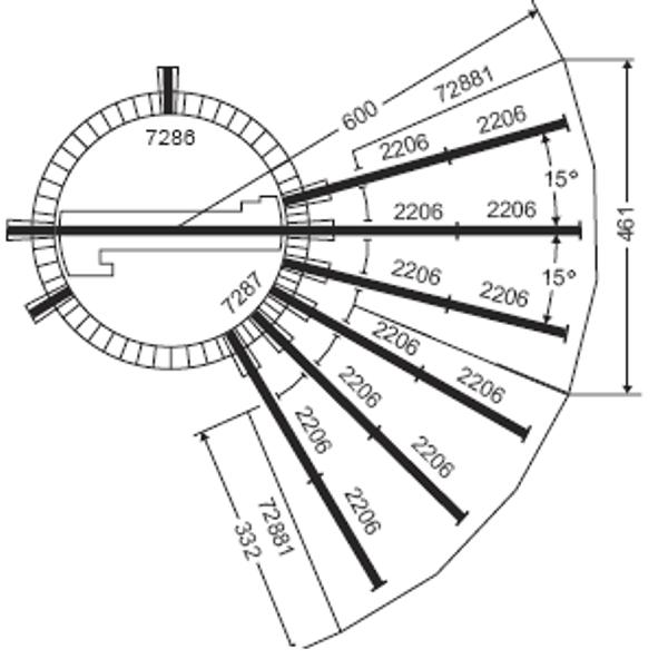
There are also available sets of 3 workshops ref. 72883 that can be coupled to the roundabout. Inside each workshop, there is space for 2 consecutive tracks ref. 2206. Several sets of workshops can be coupled together. The entrance doors to the workshop are arranged at 15º to each other. Vollmer also has workshops for this roundabout with references 45754 for 3 workshops and 45758 for 6 workshops at 15º. Fleischmann has reference 6476, a set of 3 workshops at 7.5º, although in this case, much more space is needed for them as they must be separated far from the roundabout.
 Conexión Märklin 7286 - Tres Carriles
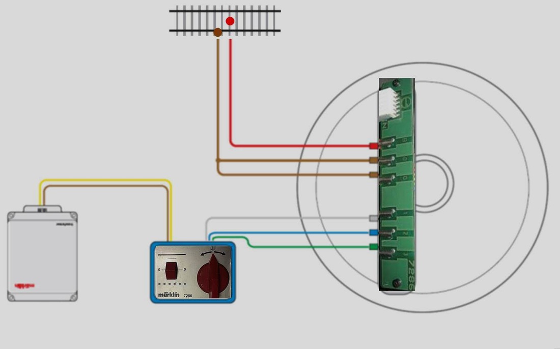
Analog Connection: Connecting the turntable in analog mode, just as it comes in its box, is quite simple. You need to connect three pieces together; the control unit that connects to the printed circuit board of interconnections and this, in turn, to the turntable via the flat cable. The control unit has 5 wires; two of them that are together, brown and yellow, need to be connected to the power of the 16v analog transformer usually used for lighting or accessories. The other 3 wires that come out together (black, blue, and green) connect to the printed circuit board at the marked positions 1, 2, and 3, that is: the black wire to connection 1, the blue wire to connection 2, and the green wire to connection 3. The interconnection board also has 3 other connections marked as [B] , [O] , [O] . The connection [B] should be connected to the corresponding
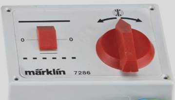
Control knobThe control knob is very easy to handle. It only has 2 elements; the vertical sliding button and the rotary knob to the left and right. The rotary knob only serves to determine the direction of movement of the bridge in one way or another. The vertical sliding button has 2 possible directions: upwards, to the position marked with a thick black line indicating continuous movement, or downwards, to the dashed line indicating step-by-step movement. By moving this button upwards and pressing it once, the bridge will operate continuously in the direction indicated by the rotary knob. It is not advisable to make more than one complete turn as there is a coil in the mechanism that will remain permanently activated and is very delicate, running the risk of burning out. If we move the button downwards, each press will move the bridge one step to the next segment according to the direction indicated by the position of the rotary knob.
 Conexión Märklin 7286 - Tres Carriles
**How does it work?**The operating mechanism is somewhat complex. Let's first look at how the electrical part works and then the mechanical part:
Electrical operation
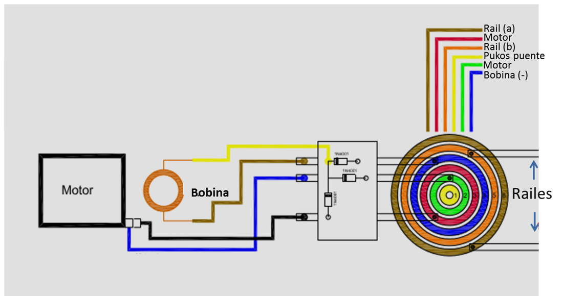
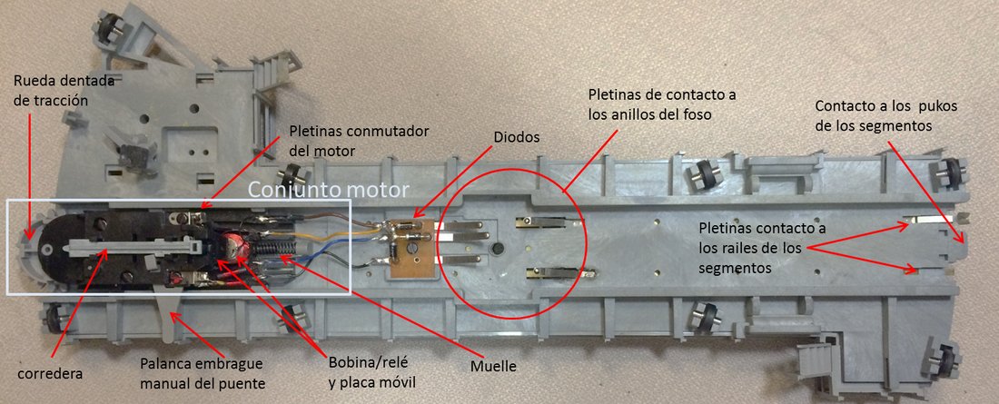
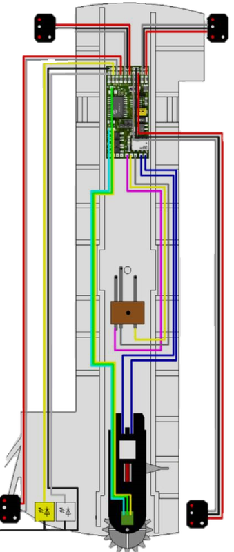
In the graph we can see the connections of the flat cable that come from the interconnection board to the contact rings located on the shaft of the pit. The bridge has plates that rub against the rings of the pit and conduct the different currents to each element: The digital current for the bridge rails (brown and orange cables) and for the pukos or central contact of the bridge tracks (yellow cable). The 16v analog current to the motor (red and blue cables) and to the coil/relay (green cable), the other pole of the coil is obtained from the diodes that rectify the direction of the current from any pole of the motor. Thus we see that for the movement of the bridge (motor and coil/relay) only the analog current is used while the digital current is used exclusively for the power supply of the bridge tracks. The plates that contact the red, green, and blue rings go to the printed circuit board with 3 diodes. This board acts as a distributor of the current to the motor and to the coil. The motor is powered with the black and blue cables. The black takes the current directly from the plate that goes to the red ring. The other pole of the motor with the blue cable takes the current directly from the plate that goes to the green ring. (this change of colors is a bit misleading but it is the actual assembly). The polarity of each of the cables will change depending on how we have positioned the rotary control for the motor to turn one way or the other. In the case of the coil, we only have one pole that takes current from a plate; it is the brown cable that takes current from the plate that goes to the blue ring. But we are missing another pole for the coil that is taken from the three diodes (yellow cable of the coil). These three diodes in turn take the current from the motor cables, meaning that any current that powers the motor in any direction will be rectified by the diodes to power the second pole of the coil always in the same direction (+). Thus the coil will act when the control is pressed on the vertical slider.
 Motor Rotonda Märklin 7286 - Tres Carriles
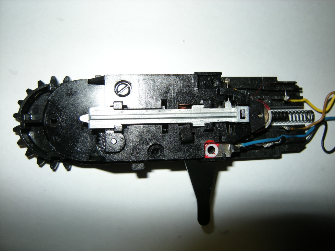
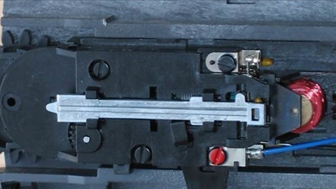
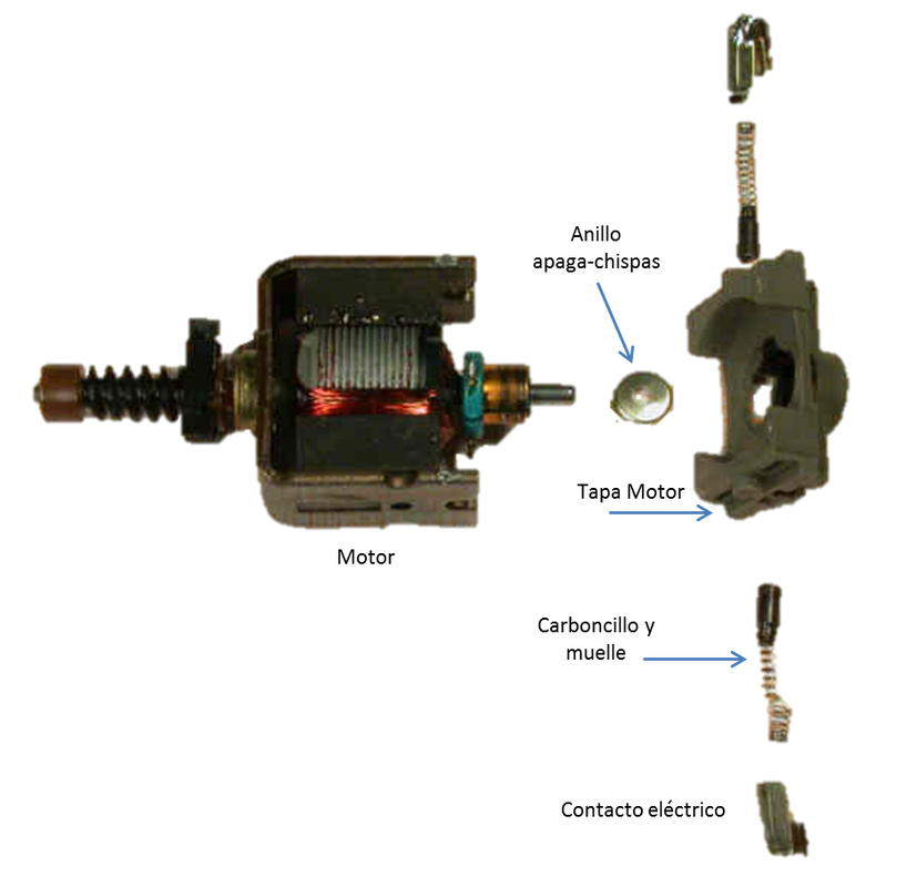
Mechanical operationThe motor/coil mechanism is quite complex, especially the coil which has several functions; but first let’s explain the purpose of this complex mechanism. Basically, the only way to control that the bridge is positioned exactly in a position with the rails perfectly aligned implies that we need an automatic locking system to stop the motor exactly at a certain point in each possible stopping position. This mechanism is a slider that locks/unlocks the motor acting as if it were a 'clutch'. The coil moves the slider and in turn, so that the motor does not try to keep turning while the slider locks it, it also moves some contact plates cutting or allowing the passage of current to one of the motor's poles. In the photograph, you can see the complete mechanism with the metal slider at the top.
 Detalle del calado de la "corredera" en la rueda dentada y la pletina resorte
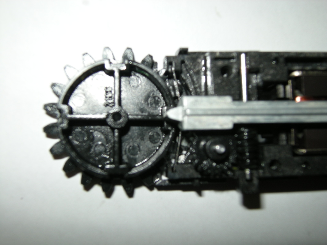
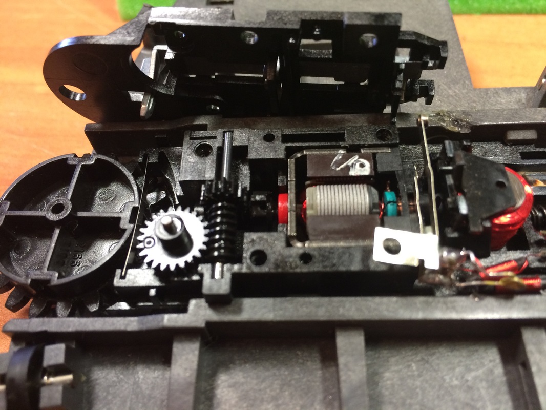
The key to locking the engine is in the gear wheel of the engine's movement transmission on the walls of the pit. This gear wheel, which is seen in the photograph, has 4 notches in which the slider will enter, blocking its movement. Each notch is a quarter turn of this gear wheel, which corresponds exactly to a single step from one segment to another of the roundabout. So when the coil acts, it pulls the slider out of the notch, unlocking the transmission wheel and therefore the engine, while pressing the motor contact plates and it begins to rotate. The slider then slides pressed by a plate on the smooth side of the gear wheel until, in a quarter turn, it fits into the next notch, forced by the pressure of said plate, thus locking the wheel and the engine. If the pulse on the control is with the sliding button up in the continuous movement position, the coil will act continuously preventing the slider from re-engaging every quarter turn, making the movement continuous. The best way to understand this operation is by disassembling the entire mechanism and observing all the pieces. Let's see it below.
Dismantling of the bridge
Manual clutch lever
extraction of the pieces from the perimeter of the roundabout
Dismantling of the central rail of the bridge
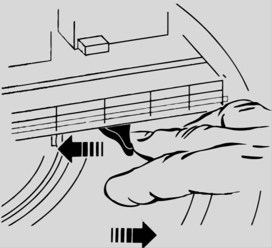
To extract the bridge from the moat, it is necessary to remove a few segments from the perimeter of the roundabout. First, we will manually turn the bridge by pressing back the manual clutch lever located under the bridge on the side of the booth. With the lever pressed back, we turn the bridge to the area that is most convenient for us to comfortably remove the necessary pieces.
To release the bridge, you must remove 6 consecutive pieces from the side of the bridge booth and 4 pieces from the opposite side. Care must be taken when removing the pieces to avoid damaging them. With a flat screwdriver, we will gently press the plastic clip that is on the inside of the piece, inward and upward. Once the pieces from each side have been removed, we will turn the bridge again (using the manual clutch lever) orienting it correctly towards the gaps of the removed pieces; the side of the booth towards the gap of 6 pieces and the opposite side towards the gap of the 4 pieces.
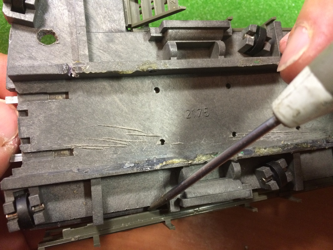
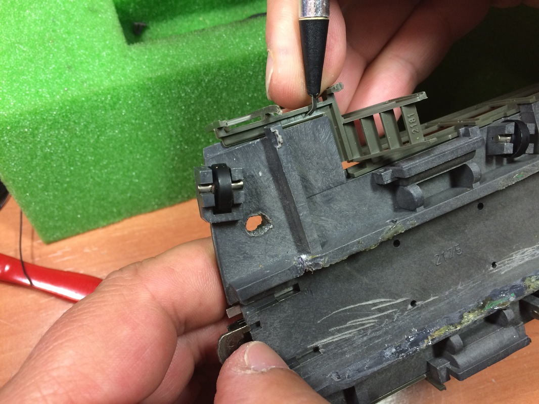
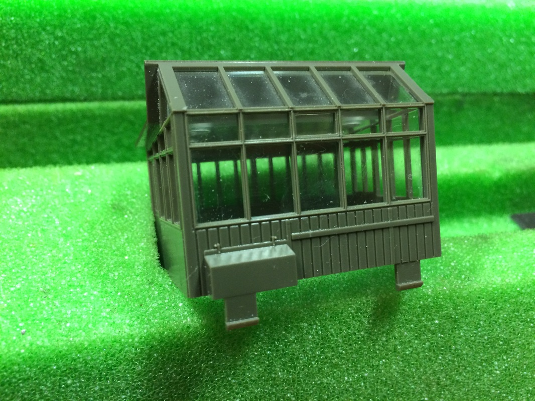
The next step is to unscrew the central screw of the bridge and remove the 2 plates between the tracks that serve as a conductor for the locomotives' skate. Now we have completely freed the bridge from its anchorage in the pit and we can remove it to uncover all the mechanism of the motor, coil, slider, etc. Some versions of the bridge instead of the 2 plates and a screw, simply have a clip that needs to be released instead of the screw. Since we need to work with the bridge upside down, it is best to remove all the parts that could be damaged; railings, cabin, traffic lights, etc. In the following photographs, you will see how they are removed to leave the bridge completely free of accidents. With a flat screwdriver, we gently pry between the bridge and the railings. The cabin is very easily removed by pressing underneath the bridge the 4 legs that hold it. The rest of the parts, traffic lights, etc. simply come out by pulling them.
Dismantling of the bridge railing
Dismantling of the bridge ladder
Detail of the bridge booth anchors
The mechanism of the bridge
In the following image we can see the bridge from the bottom with the most relevant pieces marked. Starting from the right we see some plates that serve to feed each segment of the perimeter of the roundabout that the bridge is in contact with; one for each rail and another (the plates on the top) for the "pukos" or central contact. It should be noted that the segments have current only when the bridge makes contact with them through these plates and sheets.
Rotonda Märklin 7286 - detail of the bottom part of the bridge - ( image of Three Rails )
In the red circle we have the plates that take the current from the contact ring disk of the pit that we described when we discussed the electrical operation. Then we see the diodes and the connection board to power the coil and the motor. Everything inside the white box is the [motor assembly]; a complex mechanism that is responsible for moving the bridge. This "assembly" is fitted into some side rails of the bridge and moves back and forth. The [spring] pushes it forward so that the [main gear wheel] presses and fits against the rack of the pit and when the motor operates and the main gear wheel turns, the entire bridge is displaced. Backwards it has the spring as a stop but forwards the only thing holding it are the wires soldered to the [diode board]. If we want to remove the entire motor assembly, it is enough to loosen the screw that holds the diode board, then the entire assembly will come out by pulling it outward. The [manual clutch lever] is used to move the entire assembly backward and separate it from the pit, allowing the bridge to be moved manually.
 Detalle de la corredera
We can also see the [slider] that moved by the [coil/relay] also moves horizontally back and forth, especially the motor assembly, acting on one side on the main gear, blocking or unblocking it, and on the other side acting on the [motor switch plates], bringing them together or separating them, allowing or preventing the flow of current to it. That is:
When the coil is activated, it pulls the [mobile plate] that is attached to the slider, pulling it back and removing it from one of the 4 slots of the main gear, unlocking it and allowing the motor to turn. At the same time, the slider itself, when retracting, pushes the motor switch plates together, allowing the current to flow to it. The motor and the gear begin to rotate.
When one of the 4 notches of the gear wheel, when turning, passes again in front of the slider, it will re-engage with it, moving forward and separating the switching plates, cutting off the current to the motor. As we mentioned earlier in the "Mechanical Operation" section, the 4 notches of the gear wheel are each a quarter turn apart. Each quarter turn corresponds to an exact step from one segment of track to another.
Disassembly of the "Engine Assembly"
Märklin 7286: Interior of the Motor set - ( Image of Three Rails )
The "engine assembly" is somewhat more complicated to disassemble or rather, it is somewhat more complicated to reassemble once disassembled. To disassemble it, just unscrew the 4 screws that hold the top cover of the assembly and as soon as we lift the cover we will have all the loose pieces. The cover must be removed gently as there are several pieces that may come loose from their place, in fact at least the slider and the manual clutch lever will come loose but some other internal piece may also do so.
Now we can see the motor, the reducer with the worm screw and a gear wheel that reduces and a satellite of the main traction gear to the rack of the pit. Between the main gear and the satellite gear we see a plate that presses against the main gear. This plate is a spring that pushes the slider forward when the assembly is mounted. As seen in the photo, between this plate and one of the fittings of the main wheel there is a space where a "tooth" will be introduced that is at the front of the slider which will perform the movement locking. The plate is very easy to lose and very difficult to replace so care must be taken not to lose it since with the assembly open it is completely loose. In addition, we can see the coil/relay with its movable plate at the top that also engages with the slider when mounted. And finally, we see, between the coil and the motor, the switching plates of the motor power. These plates may be somewhat different from how they appear in the photograph, depending on the year of construction of this piece but the function is the same. The slider has another "tooth" at the back that when reassembling it fits between the two plates visible in the image.
Disassembly of the Engine Assembly - (Image of F.E. - Three Rails)
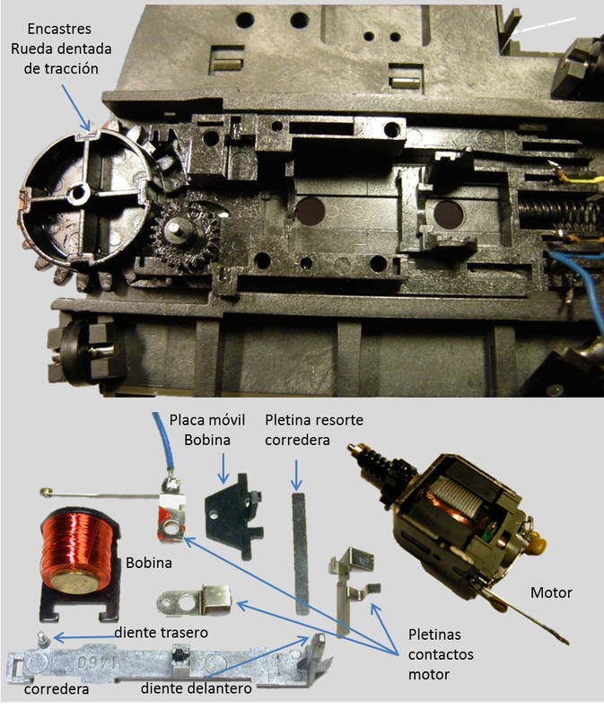
In the following photograph we can see the complete breakdown of the engine assembly. Firstly, the engine block with the reducer and the traction sprocket with its fittings. Further down, the coil/relay and the movable plate of the coil. The switching and contact plates for the motor. The ones in the photograph are from a model after 2002. (the previous ones are slightly different) The spring plate of the slider that is installed in the grooves near the traction sprocket to push the front tooth of the slider against the wheel. The slider with the front and rear "teeth". It can also be seen at the back the groove where the movable plate of the coil hooks. The motor, of which there are also a couple of different models with slight differences in design. In general, they are low-power motors and some quite noisy. (It has some inductive suppressors for electronic interference emissions.)
Reassembling the entire set is somewhat complicated. In this order, the gears, the screw conveyor, the spring plate, the motor, the coil, the movable plate, and even the motor contact plates are easy to assemble; the difficulty lies in re-aligning the cover with the slider and the manual clutch lever.
The first thing, and very important, is to turn the drive gear until one of the notches is exactly in the center in front of the horizontal axis of the motor assembly. Then, the cover must be aligned with the slider and the manual clutch lever, all at the same time. It is complicated because the front tooth of the slider must fit between the drive wheel and the spring plate, and also the rear tooth between the two contact plates of the motor, all without it coming out of place or forgetting to place the manual clutch lever (it is always forgotten). It usually requires several attempts but in the end, it is easy.
MaintenanceNeither the bridge itself nor the entire motor mechanism require special maintenance, but for everything to function correctly, there are certain things to keep in mind. The tension of the spring that pushes the motor assembly against the pit must be sufficient but not too strong, as the motor will suffer if it is tightened too much. The motor assembly must move easily back and forth. It is very important not to grease or oil the motor or its surroundings. It is an open motor; oil on the rotor will cause it not to function, to short-circuit, to operate in jumps, or to function defectively or with lower performance, which will already be serious considering how weak it is. Precautions must be taken when handling the wires of the coil or any friction or damage that may occur. It is extremely delicate, and any impact can completely damage it. The wires break with any slight handling and are not repairable in most cases, nor replaceable. We could apply some grease (not oil) to the reducer assembly if it is very dry, but very lightly, especially on the screw shaft. We can also lubricate the edge of the gear wheel where the tooth of the slider rubs a little to reduce friction, always applying the minimum possible. In the end, the entire assembly should remain almost dry.
 Despiece Motor
RepairsThe most common and complicated breakdowns to repair are those that occur in the engine or in the coil. We must know that there is no individual replacement; in case of substitution, we can only obtain a complete and very expensive engine set. Even so, there are some things we can do.
The engine
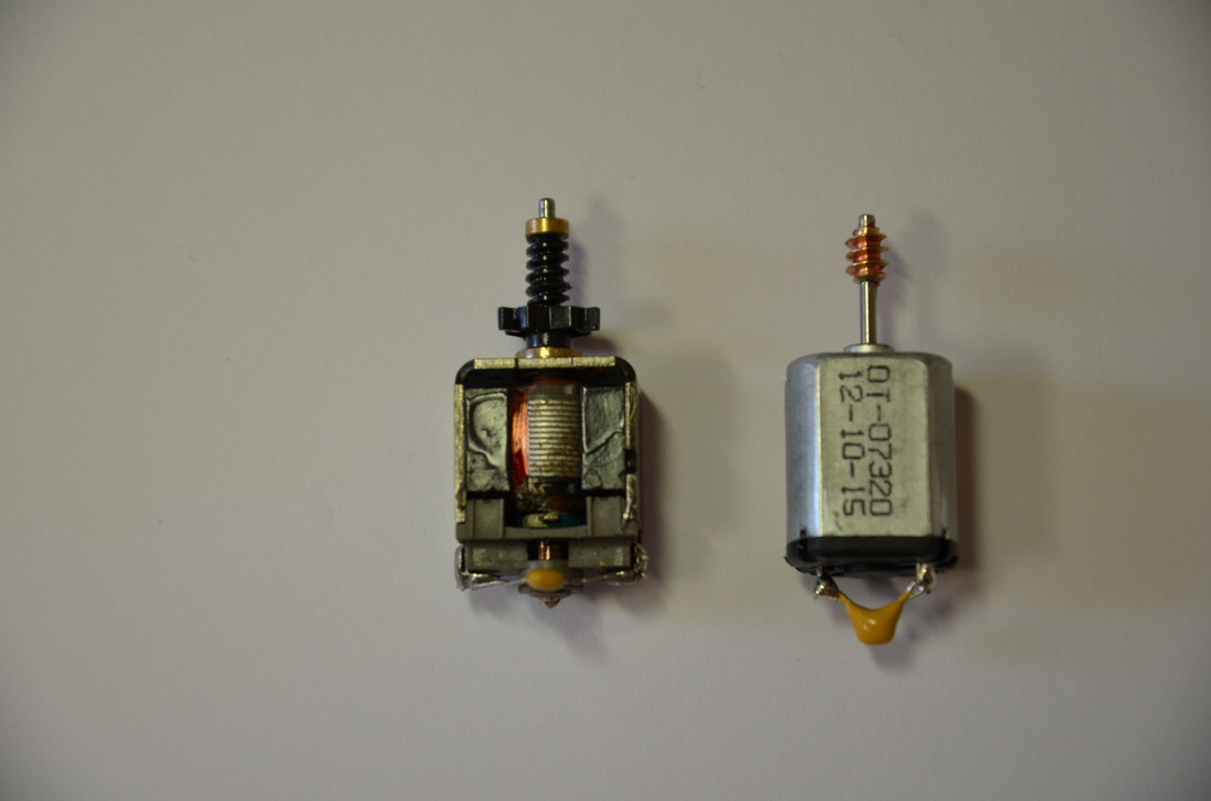
Although there are several engine models, the characteristics are similar 15v, < 200 mA.
The motor has 2 brushes that should last many years, so it is initially considered maintenance-free, but we may need to clean them if the motor does not work properly. They are very easy to remove and reassemble, but the springs that push them are extremely delicate. The springs will likely break before the brushes do. The photograph shows the position in which the parts should be removed. Cleaning is delicate but simple. In addition to the brushes, a cleaning of the rotor; polished with a polishing sandpaper (not a normal grain sandpaper) or better with a Noch 60140 clean-rail sponge (excellent). Cleaning the rotor slots is a godsend. It should be done carefully, for example, with a toothbrush soaked in isopropyl alcohol. Nothing else can be done with it in case of winding failure, unless we encounter a superficially cut wire, in which case the conductive paint could be the solution in some cases. (There is a very similar motor, but its installation requires modifying the base in an irreversible way, and it is not very advisable to carry out this intervention unless we are going to digitize the roundabout with the Sven Brandt DSD 2010 system that we will explain later.)
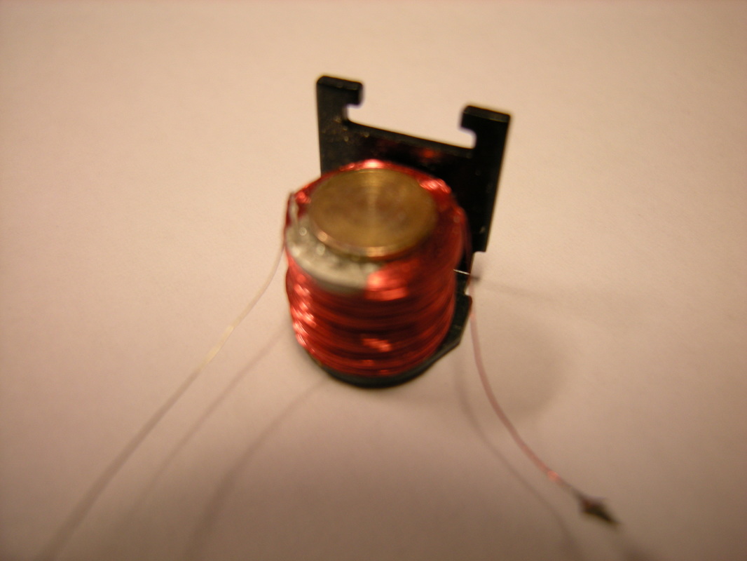
Repaired coil
** The coil**
The coil requires no maintenance. Possible failures are in the breakage of the threads. If these occur internally, there is nothing to be done. If they are superficial and of a single thread, cut flush with the coil, where we could not solder, there is a possibility of using conductive paint to try to fix it. Some have been repaired this way (see photo of a coil repaired with conductive paint). If your only solution is to rewind it, you should know that the original uses 31m of length of 0.10mm section enameled wire. With patience, it is possible to pull out the wire and rewind it with new wire.
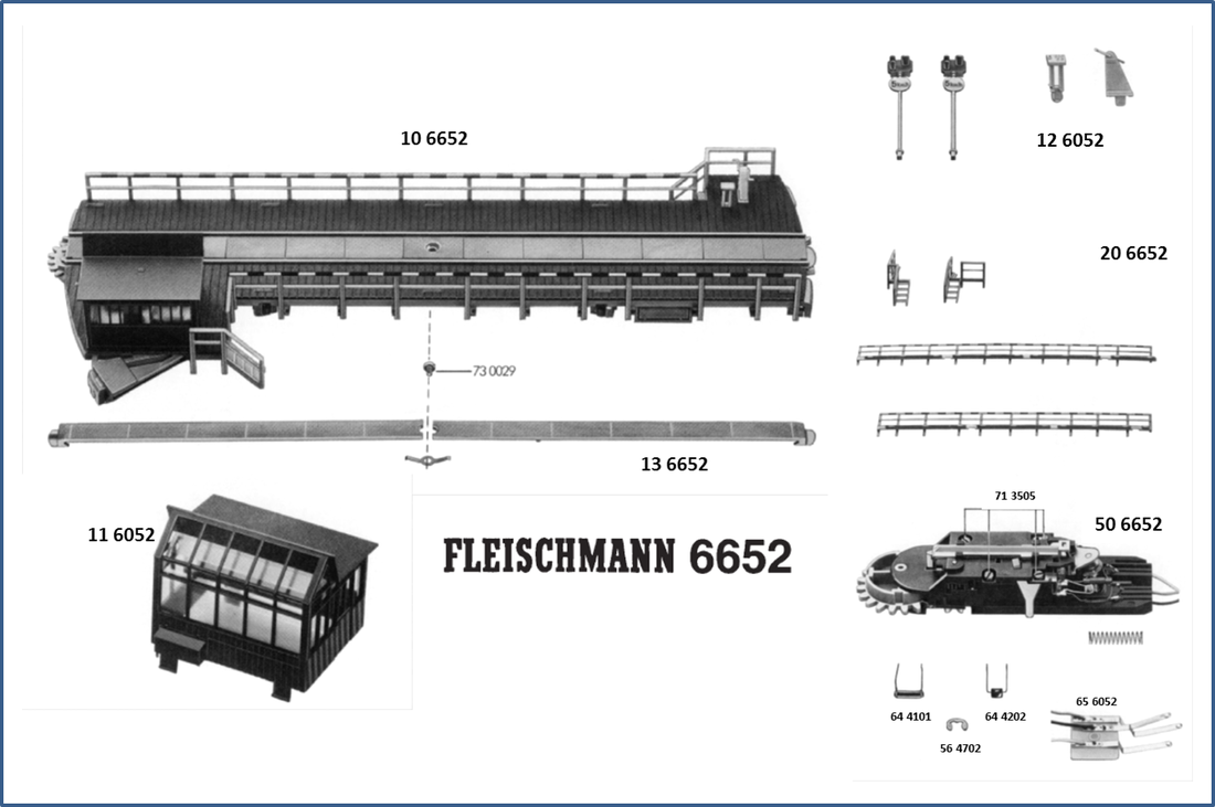
Märklin 7286 / Fleischmann 6652 Breakdown
Fleischmann 6652 BreakdownThe Märklin website does not show any breakdown catalog to order spare parts; however, Fleischmann does have the following breakdown brochure for its turntable 6652, which is equivalent to the 7286 from Märklin. If necessary,
![]()
7286-mae.pdf
File Size:
5270 kb
File Type:
Click on the document on the left to view the installation manual for the Märklin 7286 roundabout
DigitalizationMany enthusiasts prefer not to digitize the rotary table since, after all, its function is to enjoy performing manual operations with it, so the high cost of digitizing it is not worth it for them. Digitalization only aims to perform these operations automatically. Until a few years ago, the rotary table did not appear as a digital control element in control software, and even in modern digital systems, it did not either. However, this has changed recently, and today there is no reputable software that does not have this element incorporated among its functions. Thus, digitalization becomes more interesting as we can now continue to perform manual or automatic operations even at the same time, controlling this device from the central unit or from the control software. There are several digital decoders on the market to digitize the rotary table, some even with special functions. We have chosen as an example three of them that have similar characteristics; the Märklin 7687 decoder, which is the standard, the LDT decoder, which is 100% compatible with the Märklin one and has some improvements, and the Sven Brandt DSD 2010 decoder, which is also compatible with the standard and is a very sophisticated decoder even with the possibility of adding sound.
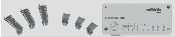
**Decoder Märklin 7686/7687
**
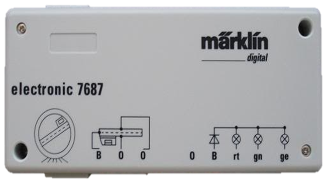
The decoder 7686 and the 7687 are functionally identical although there is a small difference in the way of connection. This decoder comes preprogrammed for the accessory switchboard 15 digital address 225. For a second roundabout, the Switchboard 14 Address 209 would need to be used and a bridge soldered on the decoder board. You can see how to perform this operation in the decoder manual that we include at the end.
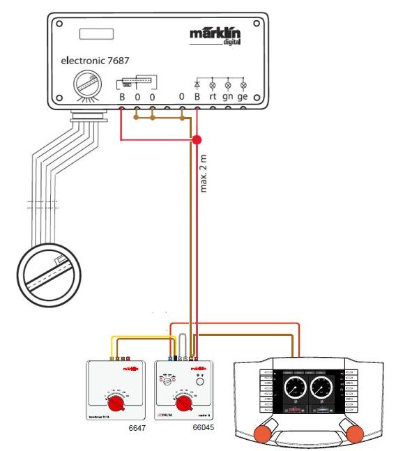
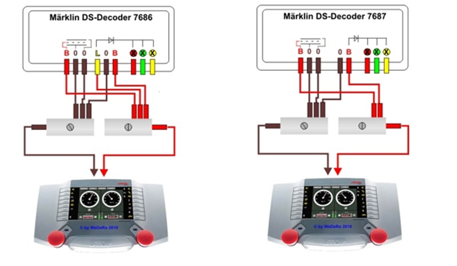
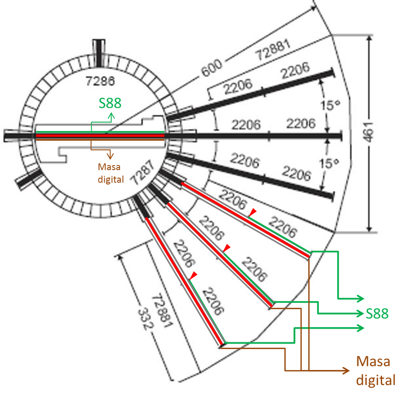
It is a device that has had bad press due to its ease of becoming misconfigured and having to be reprogrammed again, which happens too often. This is the fundamental reason, apart from the price, why other decoders have emerged that solve that problem. This decoder does not allow traffic lights to be operational nor does it have a function to light the booth so that it can be turned off and on or vary the speed of the bridge's movement. Its functionality is limited to step-by-step movement, continuous, 180º, and "Indexing" that is, jumping to a specific track by selecting its number. This implies that programming of active and inactive sectors is supported. The connection is simple in both decoders, as seen in the image. Connection "B" is the red of digital current for the bridge's pucks and the connections "0" are one for each rail of the bridge. If you want to connect an S88 to detect the occupancy of the bridge, it is enough to take one of the connections "O" and take it to the S88 instead of to ground as seen in the diagram. The three connections on the right (red, green, yellow) are only to see the status of the decoder by connecting some LEDs. The only difference between the two decoders is that the 7686 has a connection "L" and the 7687 does not have it, but in reality, it is not necessary since "L" is bridged with "B".
As can be seen, all the power supply of the turntable, both the tracks and the current used to move the motor unit is digital, so the operation is somewhat affected by this. Other decoders from other manufacturers separate the digital current that powers the tracks from the analog current that powers the motor unit. Regarding the mechanical part, no modifications are necessary except that the manual control and the interconnection board will no longer be usable, and we will have to move the turntable using the digital central or through the control software.
Decoder LDT
TT-DEC
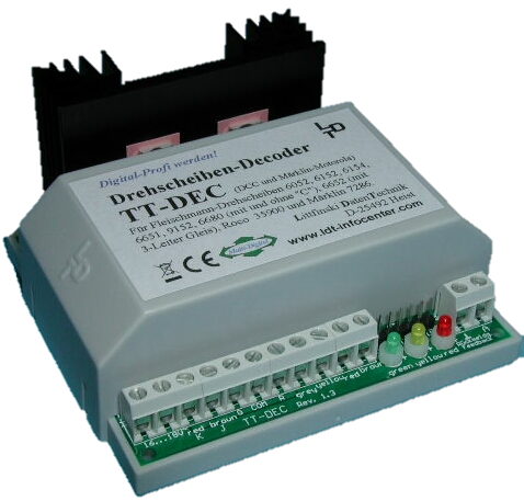
This decoder is fully compatible with the Märklin 7687 with the advantage of having a lower price and not being deprogrammed like the Märklin one. It is also preprogrammed with the same digital addresses as the Märklin one (switchboard 15) but has the advantage that to program a second turntable for Switchboard 14, it is not necessary to solder any bridge on the board like the Märklin one, but it can be reprogrammed. The connection is made using the standard cable that comes from the turntable. It also has the advantage that it can use digital current only for the tracks while for the motor set it can use analog current from another transformer, for lighting for example. In addition, it has two feedback outputs to connect to an S88 module. One of them is the same as the 7687, that is, the signal that comes from one of the rails, but it also has another that informs when the bridge has reached the determined position. It also supports, like the Märklin one, Indexing, that is, programming which tracks have connection and which do not, allowing direct commands to go to a certain sector in addition to standard step-by-step movements and continuous or 180º turns.
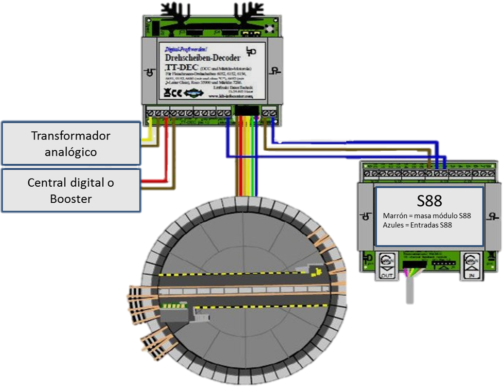
With this decoder, just like with the Märklin one, it has not been planned to make the traffic lights of the roundabout operational nor to illuminate the booth with the possibility of turning on/off from the digital control, however it does have a potentiometer to regulate the rotation speed which will be fixed throughout the entire journey. As seen in the graph, the connection is very simple and completely standard so no mechanical modification is needed in the roundabout. Another advantage of this decoder is that LDT sells it fully assembled with or without a box or even sells the circuit board and its components to assemble it oneself at a much lower price. This guarantees the availability of spare parts for the components in case of need.
**Decoder Digital-Railway **DSD 2010
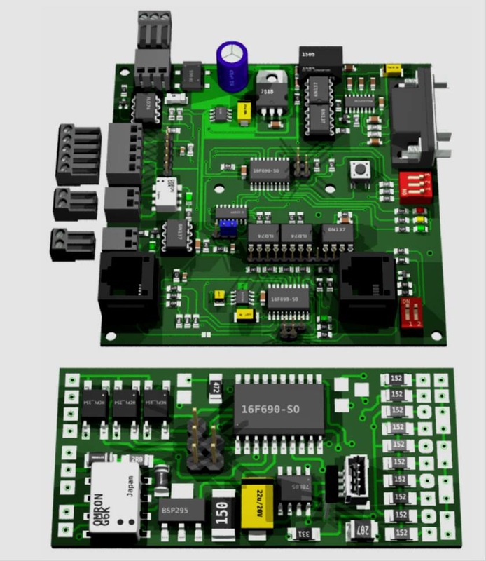
Decoder modules out of the bridge and in the bridge. Image from Digital-Bahn
Märklin motor and Tillig motor compatible with slight modifications on the bench
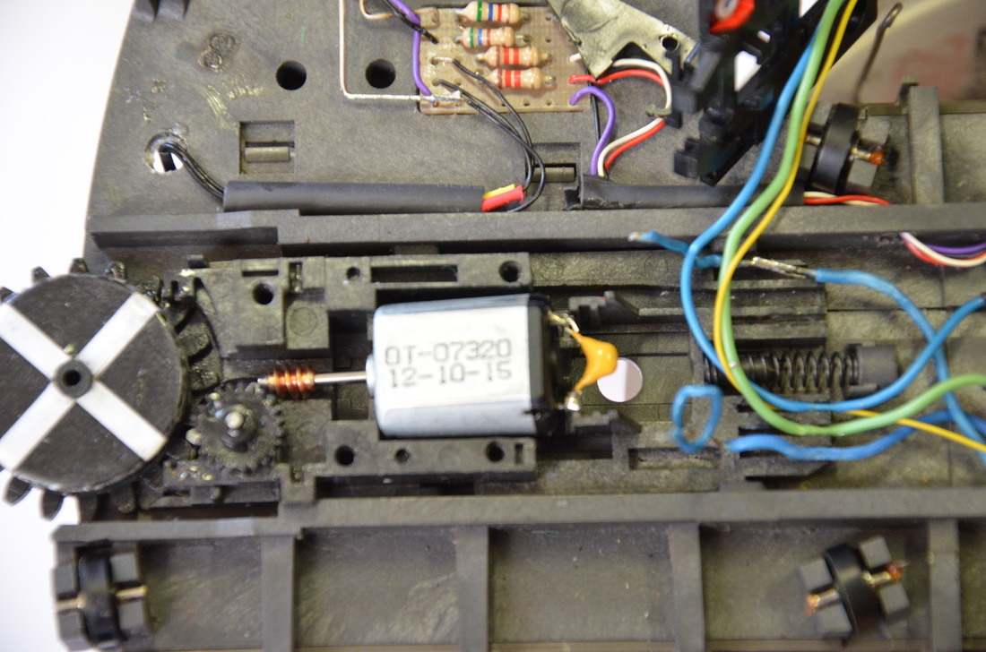
Modifications to the bench for the tillig engine
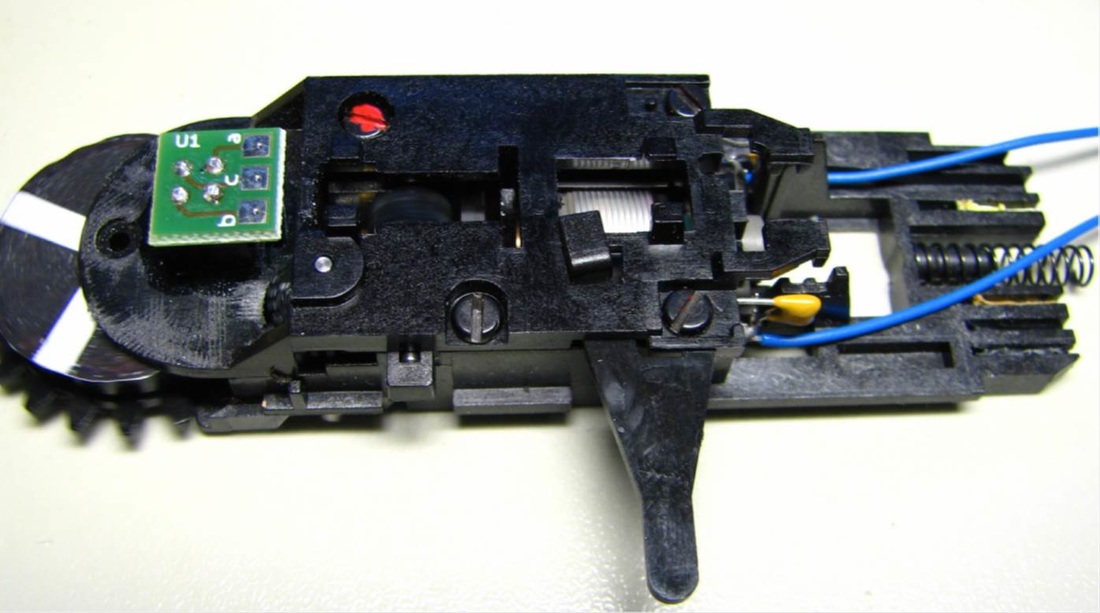
Installation of the infrared sensor and 4 recess reflectors in place of the slide and the coil/relay
Installation of the decoder module under the bridge, traffic lights, and double lighting of the booth.
This decoder is very special and sophisticated. It is an evolution of the previous DSD v1.4 of which we have very good experience in Tres Carriles. It is compatible with that of Märklin although with some differences in a couple of digital directions since it takes advantage of some of them for other things such as turning on or off a light installed in the shed. This light does not exist originally, it must be installed. A rotating light can also be mounted on the roof. The decoder will control them. However, it is necessary to completely modify the motor assembly by eliminating all the automatic mechanism of the coil, slider, motor contact plates, diodes, etc., and leaving exclusively the motor with its cables connected to the distribution board but without diodes and nothing else. This, which seems very "daring", substantially improves the performance of the motor by freeing it from many possible breakdowns and giving it mechanical simplicity, allowing even alternatives to install another motor of better performance and cheap without having to buy the entire mechanism. (for example, the Tillig switch motor fits in the motor assembly with small modifications to the bench (see photo) An infrared sensor must be installed instead of the slider and an adhesive on the gear wheel with 4 marks on the fittings to perform the locking electronically instead of mechanically. Some small holes will also need to be made under the bridge, well concealed, to wire the new decoder, and all the functions that will be added: 2 or 4 signals, additional retro contacts, and shed lights or even a sound module. Viessmann or Märklin signals can be installed on the bridge, replacing the temporary ones, since this decoder can control them. It has its own connection to the S88 BUS so it can fully control both the occupancy of the bridge and its position. Moreover, you have enough sensors to make 2 cuts in one of the rails of the bridge and install 3 sensors on one of the rails; 2 Stop, one on each side of the bridge and one central to have a totally precise control of the locomotive's stop. A Hall sensor can also be installed under the bridge to determine its final position and reset its position automatically in case of failures. In addition, the decoder board that is installed under the bridge has a socket with "Susi" connection to plug in a Uhlenbrock sound module with the real sound of the turntable. It has two adjustable speeds; a fast speed when it has to move several sectors in a row and a slow speed when approaching the sector where it has to stop. The sound is synchronized with both speeds. Finally, a new manual control panel can be installed, electronic, which fully recovers manual control while being managed digitally. It comes with its own control and programming software but is also compatible with the most well-known control programs such as iTrain, RR&Co, WindDigipet, RocRail, etc. Can you ask for more? The price of all this is not much higher than that of the Märklin decoder, not counting the extra for the Uhlenbrock sound module. The installation requires a module under the bridge and another module that is installed outside the turntable and communicates with the previous one with the standard cable that comes from the contact rings of the pit. Optionally, another module can be installed separately for the electronic manual control panel. Also optionally, the Uhlenbrock sound module can be installed plugged into the module that is under the bridge.
One of the advantages of the decoders from Sven Brandt (www.digital-bahn.de) is that they sell the decoders fully assembled ready to install in the roundhouse, or if preferred, in parts, that is; the board made but all the components separately to solder them oneself as well as program the "pic". It should be noted that many of the components are SMD so they are not easy to solder, however the price is greatly reduced. The advantage is that there are spare parts for all the pieces. They also provide a control and diagnostic program for free. One of the disadvantages is that everything is in German, both the assembly instructions and programming instructions although they are very graphic.
The video on the left is a good demonstration of how the roundabout looks after being digitized with this decoder. Finally, it is important to know that these modifications are irreversible; but seeing the results, why would we want to go back?
**Other digitization methods
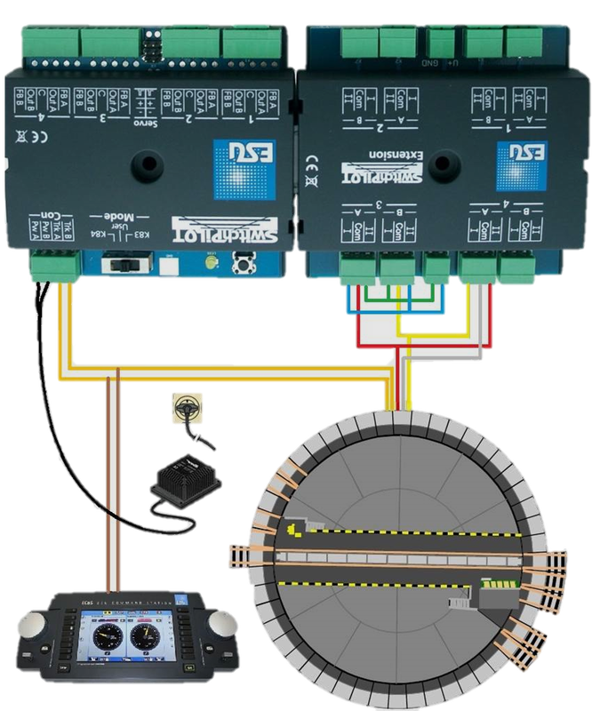
**The Märklin turntable can also be digitized with an accessory decoder type "Switchpilot + SWP Extension" as seen in the image on the left or even with an ESU Lokpilot locomotive decoder (see at: http://www.esu.eu/en/support/tips-tricks/drehscheibenumbau/).These methods could be said to be alternative and do not offer complete functionality as specific decoders do since they cannot direct the bridge to a specific output, that is, they do not have indexing, they can only perform step-by-step movements or continuous rotation. There is a lot of information on the web regarding this, but we have decided to focus our article on specific decoders with complete functionality and the most used among enthusiasts.
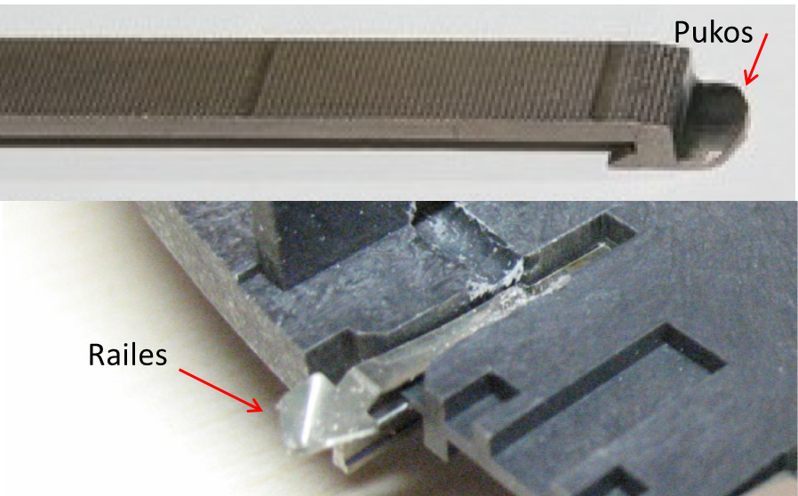 Imagen de Digital-Bahn
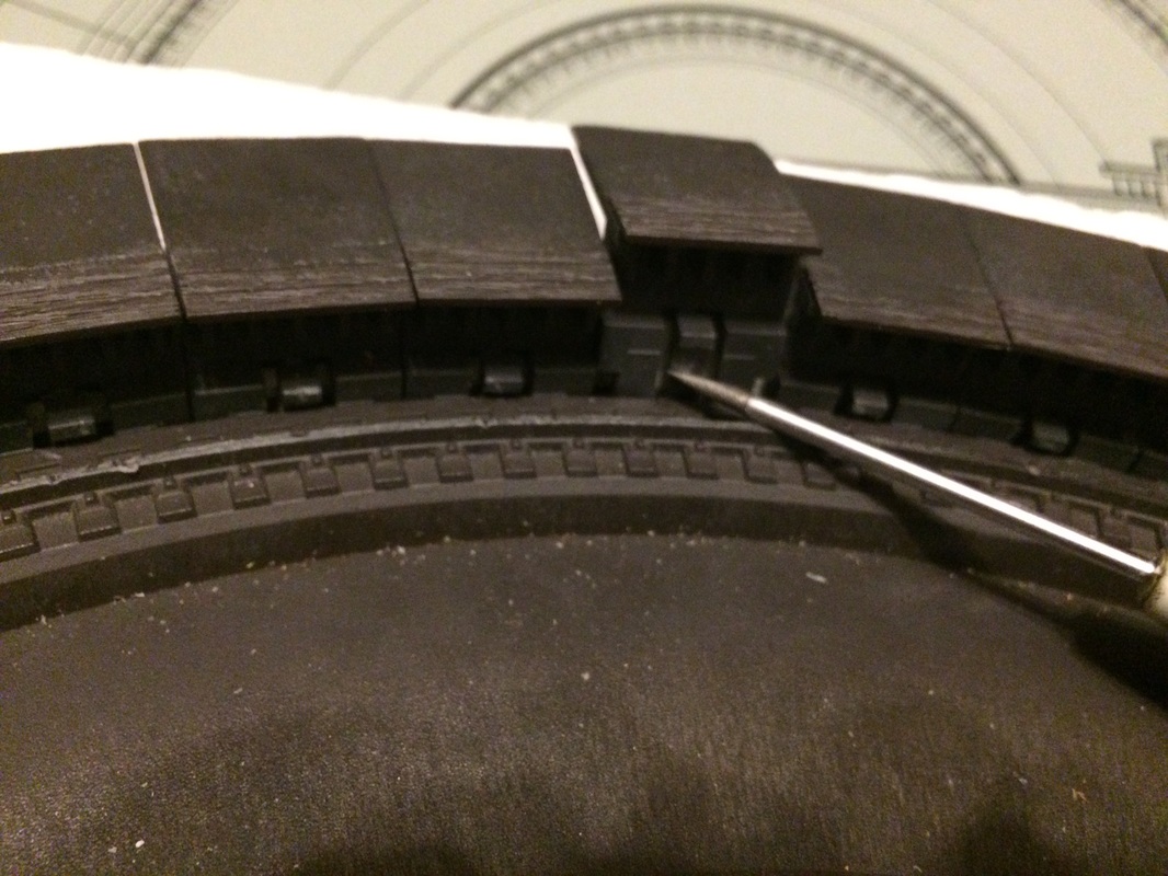
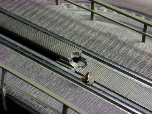
Necessary improvements for any digitization method Regardless of the digitization method we choose, there are certain things that should be done in the access tracks to the pit. As we mentioned above, the track segments around the pit are not permanently powered. This results in the siding tracks connected to the turntable always being disconnected from the digital power, so any locomotive on them will be off. These track sections of the pit only have power when the bridge passes right in front of them, as it is the bridge that supplies the power through the plates seen in the photo. This system makes sense in the analog system but not in the digital system. Ideally, each siding track sector that connects to the pit should be powered individually. It doesn't matter if we power the sectors of the pit or the siding tracks themselves since they are connected to each other (for convenience, in case it is necessary to remove the pit from the board for repair, etc., it would be better to power the tracks that connect to the sectors of the pit, to avoid the cables getting in the way when removing the pit from its place). This way, we will have permanent power in the locomotives that are on the siding tracks. The problem is that by doing this, the bridge, when turning, rubs against the plates in the track sectors of the pit, and sometimes a plate from the rails rubs against the central contact (which is now powered), causing small short circuits that can even damage the motor or the decoder.
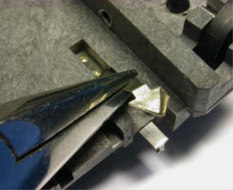 Imagen de Digital-Bahn
To avoid this, it is advisable to slightly bend the strips of the rails downwards so that they do not rub against anything. They are no longer necessary since we now have all the segments powered individually. This should be sufficient, although it could still happen (not always) that the central contact of the pukos of the bridge rubs against some track contact of some segment. If this happens, we could even trim the tip of the contact of the pukos, although this is a somewhat more drastic measure. Often, these rubs occur because the pit is not well leveled. Before trimming the tip of the contact of the pukos, it is advisable to ensure that the pit is perfectly leveled and that it is truly necessary to do so. If we use the digital control with S88 feedback, we will need to have one of the rails of the bridge isolated and connected to the S88. But, since we have now powered the track sectors of the perimeter of the pit independently, when the bridge passes over one of them, the strip of the isolated rail will make contact with the perimeter sector and we would have a false occupation of the bridge. If we bend the strips of the tracks of the bridge, as we explained earlier, we will also avoid this problem.
We will also need to isolate and connect a rail from one of the sections of the sidings to the S88. This is not complicated and is done just like with any other section of track that is connected to the S88. The only precaution to take is that we do not leave any rail from the perimeter segments without power. The most convenient thing is to isolate the rail from the last section of the siding while the track that remains between the perimeter sector and this one should have power on both rails, thus ensuring that the perimeter sector is always well powered.
Digital control software and programming of the decoder.
Both the Märklin 7687 decoder and the LDT TT-DEC and the Digital-Bahn DSD-2010 are supported by the most common control programs, RR&Co, iTrain, WinDigipet, Roc-rail, and others.
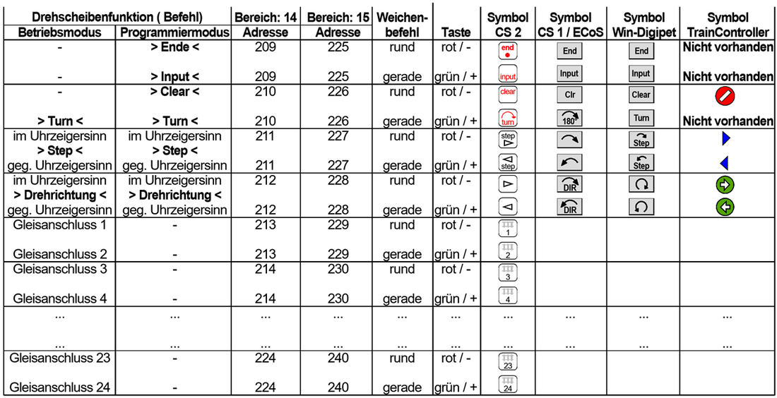
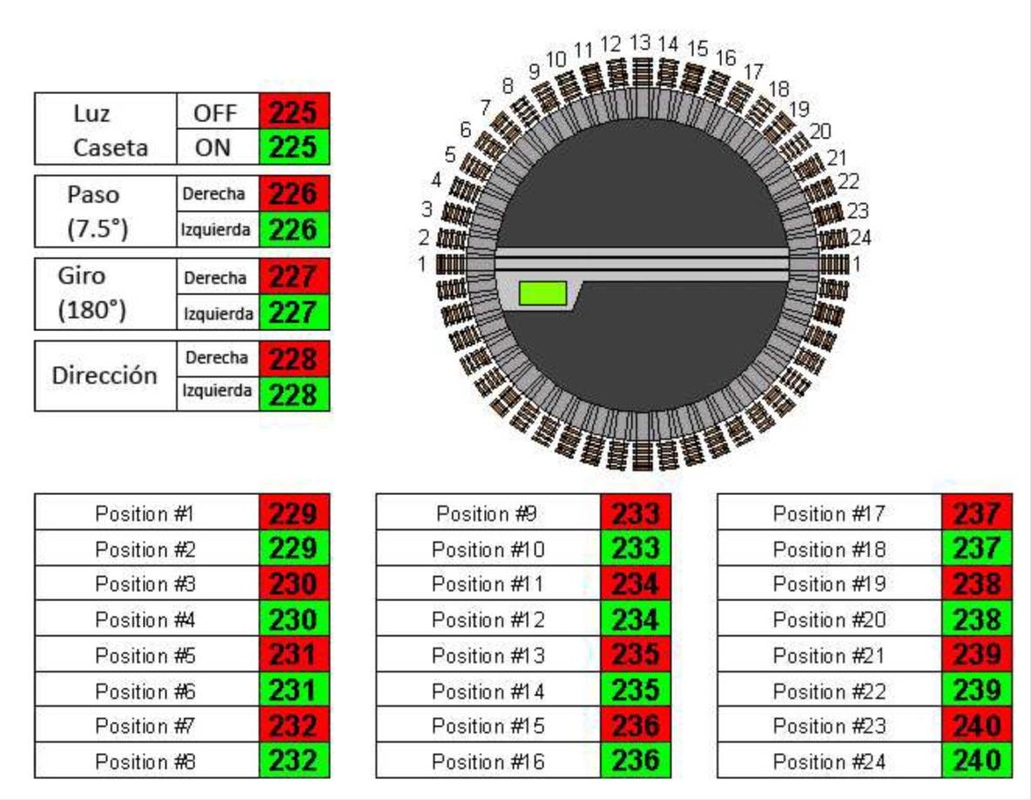
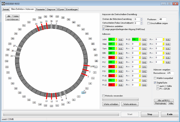
Everyone uses the same configuration of digital addresses. For the switchboard 15, the first digital address is 225, which will be the one to use when registering the roundabout in the control software or the central. If we want to use a second roundabout, we should use switchboard 14, meaning that the first address and the one that identifies the device would be 209 in that case. In the attached tables, we can see the digital addresses with the corresponding functions in each decoder. As can be seen, they are exactly the same in all cases except for the DSD 2010, which uses address 225 for the lighting of the booth and has the functions of addresses 226 and 227 swapped; the rest is the same. The Märklin decoder and the TT-DEC from LDT are programmed using the buttons on the Switchboard or the digital central. The DSD 2010 has free download software and is programmed from the PC, in addition to performing diagnostics on motor behavior, etc.
Märklin 7686 / 7687
TT-DEC
DSD 2010
Procedure for the programming of the indexing of the roundabout
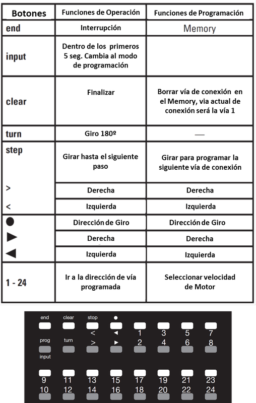
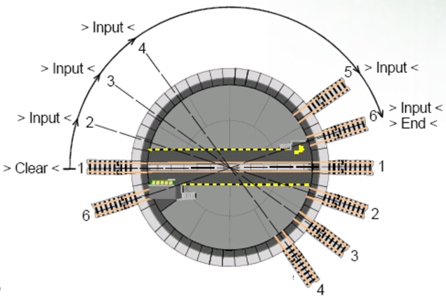
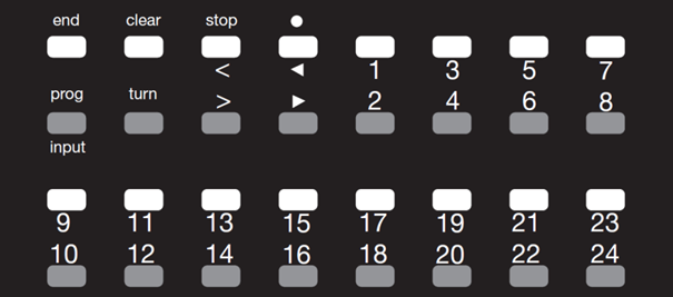
Both the Märklin 7687 decoder and the LDT TT-DEC use this procedure to program the connected tracks. (The DSD 2010 uses its own software to do this). The position and the number of active tracks must be entered before the first use of the turntable or after changing or expanding the active access tracks. This is handled by a simple programming procedure with the digital accessory controller. (Keyboard or control panel of the turntable in the Digital Central)
The programming starts with the button [INPUT]. To do this, this button must be pressed within 5 seconds after the digital controller has been turned on. Any other button will stop the programming mode.
The digital controller is turned on by pressing the [STOP] and [GO] buttons (on the Märklin Control Unit) or by pressing the [STOP] button twice (on the Central Station). The start of the programming procedure is indicated by the flashing yellow light and the turntable moving to the position of the selected track 1. An acoustic signal will sound and the yellow light will continue to flash.
If it is supposed that another track connection should be number 1, you must go to that track with the [STEP] left or right buttons. This track connection will be stored in memory by pressing the [CLEAR] button and the previous track connection will be erased from memory.
Now you can continue with the following additional track connections by pressing the [STEP] button and/or the [INPUT] button to store that connection. Once all desired track connections have been entered, the programming procedure ends by pressing the [END] button. The complete configuration of the turntable will be stored in memory and the turntable bridge will go to track 1.
If it is necessary to make corrections or changes later, the programming procedure must be repeated starting again with route 1. The data will remain stored in memory even after turning off the digital system.
Roundabout Configuration in the control software
Each Control Program has its particular way of configuring the roundabout, but they all have in common the elements that need to be introduced into the program; The digital address 225, or 209 for a second roundabout, the Digital Central used, the decoder, the tracks with connection for indexed control, estimated time/speed of the bridge's translation whether step by step or continuous, sensor or sensors for bridge occupancy, etc. Here we can see some examples of how it is done in iTrain (in RR&Co, WinDigipet, etc. it is very similar).
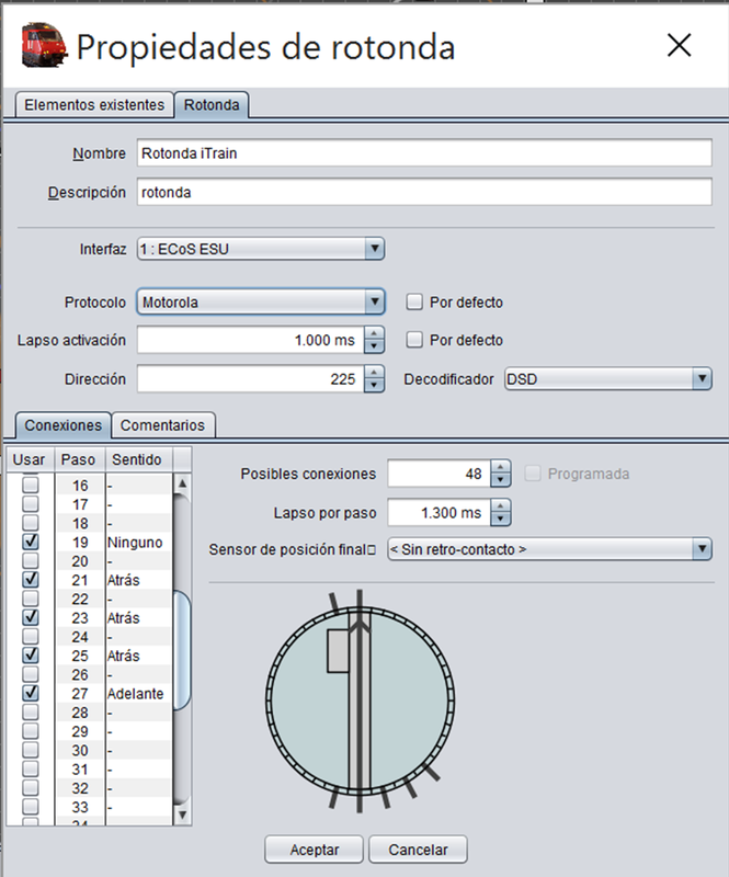
Properties of the roundabout in iTrain (image of Three Tracks)
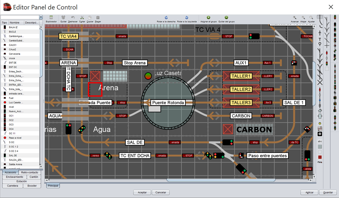
Control panel with the roundabout in iTrain - (image of Three Tracks)
A very important value is the translation speed ("Lapso por paso" in iTrain). As it is a relatively precise data, it is always advisable to set a value that allows the bridge of the Program to arrive slightly later at its position than the real bridge to avoid conflicts and to give output or input to the bridge to a locomotive when it has not yet fully reached its position in reality. We can also parameterize a delay in the activation ("Lapso de activación" in iTrain).
All programs support indexing, so you just need to mark the numbers of the tracks with connection. As for the sensors, there are two; the occupancy sensor that can be used in all decoders and the end position sensor that can only be optionally handled by the TT-DEC and the DSD 2010. The end position sensor is not a mandatory sensor, but it can be useful if our turntable is not easily accessible, as if something fails and desynchronizes, passing through the position sensor will automatically resynchronize. The occupancy sensor or sensors are part of the bridge section of the turntable. In iTrain, it is not configured in the properties of the turntable but in those of the bridge section. Additionally, in iTrain for the lighting of the shed, we need to create an accessory "light" with the address 225.
Note: in iTrain to access the properties of the roundabout you have to click on the pit of it in the control panel. To access the properties of the bridge's cantilever you have to click on the bridge of the roundabout in the control panel.
Fernando Escribano (Three Rails-August-2015)

Translation of this article into Italian and adaptation of text and photos by Stefano Spina from Märklinfan Club Italia, who has kindly provided us with this document.